After the overwhelming success of last month's Hacker Potluck, we invite you
to join us at 23b Shop's next SoCal Hacker Potluck on March 19th.
POTLUCK: Bring something to eat, or whatever you want. Do think about it. We do get down with some good food and encourage you to do so as well -- for instance, delightful crepes were made on the spot last month at an Extemporaneous Crepe Workstation set up by one of our industrious attendees. We challenge you to be as amazing as this.
WHO!? read http://shop.23b.org, http://www.facebook.com/23bOrg
DO WHAT?: You are welcome to come have or make dinner, present a presentation, hang out and listen, gawk, do whatever it is you do, find and talk with someone doing way cooler stuff than you are doing, mingle, snipe bids, rant and rave, leaflet, throw business cards, bring minions, dance and sing, etc. Present a recent project to the group using multimedia resources. Bring video of your latest project, or the project itself. Network with some of the finest people in your area.
DON'T WHAT?: This isn't a work night for noisy machine tools, but we are a workshop so if you find the need to work on something for great win, we may accommodate you. If you know someone who is doing outlandish or amazing things and hasn't come here, we encourage you to kidnap them and make them entertain you here. Definitely make sure you don't default to being a merdone.
TOOLS:We have a microwave, an amazing Signor Cappuccino coffee machine (*NEW * retro find, just brought in this month), a wicked old angry hot plate, an oxygen-acetylene torch or propane torch (...think of the Creme Brulee you could make!), a laptop, Mobile Club sound system with flashy lights, and projector, and whatever other items or tools you bring. Ask someone in charge if you have something in mind, and we may help to support your
arbitrary and capricious requests.
Tiny bicycles are always available; ask someone who knows!
spectator -- this is the one place where people want to see your work and hear about your wild-eyed theory, no matter how kooky or mis-concocted.
WHERE and WHEN?: 418 E Commonwealth #1, Fullerton, CA (behind Stages Theatre and Pizza Hut. 1 block E of Lemon) Saturday, March 19th. 6pm until we are done.
See y'all there!
Arclight

20110317


More Access Boards on the way
We've found another budget printed circuit board supplier that is USA-based. They have a nice special running through July 31st, so we ordered 10 more access controls with some more minor improvements.
Check out:
Flashline Electronics
Arclight
Check out:
Flashline Electronics
Arclight
20110204
SoCal Hacker Potluck!
SoCal Hacker Potluck!
---------------------
Please join us at the 23b Shop for big fun at our new SoCal Hacker Potluck and discussion.
Bring a friend, or more, and try to let us know if you plan to show up.
TLDR: Potluck, Thurs, Feb 10th, 2011, 6pm or so.
WHERE: 23b Shop, 418 E Commonwealth #1, Fullerton, CA 92832
WHERE!? (East of Lemon ~1 block, behind Pizza Hut)
FOOD:
- Bring something to eat and share. Plan on bringing enough food to feed several people and you can't go wrong.
- Of course, making something to bring is best, but if you don't make food it's fine to pick it up.
- Try to avoid the inelegant 'bag of chips' solution, unless you made bomb-ass salsa and need something to pick it up on.
- If you're stuck on what to bring, use this E-Z cheat sheet (or bring whatever you like)
Last name starts with A-M = entree, last name starts with N-Z = side dish or dessert or drinks
- Gourmet food trucks meet right down the street, 1501 S. Lemon St. Fullerton, CA 92832. About 8 trucks are usually there Thursdays from 5-9.
NONFOOD:
- There will certainly be a heated discussion, tech demonstration, presentation, or something. Let us know if you have something you'd like to formally do for or to the group, or just show up with stuff.
- There may be clown bike jousting, sharkfighting, or a steel cage machete battle after dinner.
- Feel free to bring a project or something you did (or want to do) for show 'n' tell.
- We have internets. We can also host slideshows and video and loud noises if you want.
- What else would you like to see at a hackerspace pot luck? Bring it, and there it'll be!
---------------------
Please join us at the 23b Shop for big fun at our new SoCal Hacker Potluck and discussion.
Bring a friend, or more, and try to let us know if you plan to show up.
TLDR: Potluck, Thurs, Feb 10th, 2011, 6pm or so.
WHERE: 23b Shop, 418 E Commonwealth #1, Fullerton, CA 92832
WHERE!? (East of Lemon ~1 block, behind Pizza Hut)
FOOD:
- Bring something to eat and share. Plan on bringing enough food to feed several people and you can't go wrong.
- Of course, making something to bring is best, but if you don't make food it's fine to pick it up.
- Try to avoid the inelegant 'bag of chips' solution, unless you made bomb-ass salsa and need something to pick it up on.
- If you're stuck on what to bring, use this E-Z cheat sheet (or bring whatever you like)
Last name starts with A-M = entree, last name starts with N-Z = side dish or dessert or drinks
- Gourmet food trucks meet right down the street, 1501 S. Lemon St. Fullerton, CA 92832. About 8 trucks are usually there Thursdays from 5-9.
NONFOOD:
- There will certainly be a heated discussion, tech demonstration, presentation, or something. Let us know if you have something you'd like to formally do for or to the group, or just show up with stuff.
- There may be clown bike jousting, sharkfighting, or a steel cage machete battle after dinner.
- Feel free to bring a project or something you did (or want to do) for show 'n' tell.
- We have internets. We can also host slideshows and video and loud noises if you want.
- What else would you like to see at a hackerspace pot luck? Bring it, and there it'll be!
23b Shop T-Shirts
Visit http://danozano.spreadshirt.com/ and pick up a 23b Shop shirt or two in any color. There are several designs and many colors available. The quality of the transfer is superior -- this is a tangentially cut logo made in layers and bonded to the shirt, not an inkjet or screenprint. The shirt will last a very long time with minimal wear.
20110120
Our largest Arduino shield evah

So the new boards from 4pcb.com came in, and I got Open Access Control 2.0 completed. It works great, and the PCB actually seems to have no layout mistakes.
After spending about $500 on materials for the prototype and first 5 boards, it's exciting to finally see some results.
With any luck, this will help jump start more hackerspace access projects.
The folks at Pumping Station One have also new
wiki site for this sort of thing at www.hackcess.org.
For those that are not familiar with the project, this is an effort to make an affordable, open source door/building control available to everyone. It's based on the Arduino, and supports 2 door readers, 4 alarm/monitoring zone inputs, and 4 output relays. The main work has been making it robust, protected from surges and accidents, etc.
 On another note, I got the urge to build an impulse sealer and pack up a kit to send to Black Lodge in Seattle. This is what $2.00 worth of Nichrome wire and a 6A lab power supply will do to a polyethylene bag. Woot!
More pictures:

The revised Eagle CAD files, plus a full bill of materials and notes are up on the code site, and kits will be offered shortly. W00t!
Arclight
20110111
Open Access Control v2.0
After a lot of delays, we have now sent the PCB for Open Access Control 2.0 out for fab. We have added the following features:
-Reduced component count
-On-board 5V switching power supply
-Improved circuit protection with MOV and TVS diode
-Opto-isolator layout can use NEC PS2501-1,2,or4 parts
-Better mechanical layout
-Full 5A continuous trace rating on all relays, 10A contact rating
See the pic below:

Full source code and drawings:
Open Access - Google Code Site
Arclight
-Reduced component count
-On-board 5V switching power supply
-Improved circuit protection with MOV and TVS diode
-Opto-isolator layout can use NEC PS2501-1,2,or4 parts
-Better mechanical layout
-Full 5A continuous trace rating on all relays, 10A contact rating
See the pic below:

Full source code and drawings:
Open Access - Google Code Site
Arclight
20101127
Moving heavy equipment with your mind
This book was written in 1922 by an artillery school, and includes lots of info on hoisting and moving huge, heavy, delicate machinery, like cannons or machine tools or overturned/stuck vehicles. The book covers knots, leverage principles, and some of the basic tools that can be created to help the task.
Mostly you will be using manpower and simple leverage multipliers of all kinds, along with some good thinking about what you're doing. Thus the 'mind' part. Unfortunately they don't cover pure telekinesis in this volume; I'm still looking out for that book.
http://www.archive.org/details/mechanicalmaneuv00coasrich
Mostly you will be using manpower and simple leverage multipliers of all kinds, along with some good thinking about what you're doing. Thus the 'mind' part. Unfortunately they don't cover pure telekinesis in this volume; I'm still looking out for that book.
http://www.archive.org/details/mechanicalmaneuv00coasrich
20101126
Rotary to linear motion with wooden gears
OBJECTIVE
Build a robust, accurate rotary-to-linear motion transfer box within a weekend, without spending any money.
PLAN
Some projects need an element that moves in a straight line, but this is not always as easy as getting rotary motion straight from a motor, pedals, or crank.
To accomplish this, I read online about mechanical linkages and selected a hypocycloid linkage. It has a very elegant and simple design, with a long linear travel for a small size. Rotary input (like a hand crank or drill) applied to the central shaft is converted to straight line motion across the diameter of the ring gear. The linear motion will be as long as the ring gear is wide.
BUILD
I hand-cut two plywood gears on the bandsaw and built a frame to run them in. The ring or internal gear has 32 teeth, the round gear has 16 teeth. Using powers of two ensures both good support from the spirit world, and harmony with the geek nature.
My gears were cut from a paper pattern generated with the free online gear calculator at http://woodgears.ca/gear_cutting/template.html , which I printed out and glued right to the plywood.
According to the site's gear-making recommendations, this is sometimes a problem with laser printers -- though not with inkjets, since they have tighter registration requirements. I used a laser printer and measured the gear patterns in several places to ensure that the laser printer didn't stretch the image in any direction.
All parts were cut by hand on a bandsaw, trimmed by hand (very little) with a wood file, and finished and lubed with paste wax. 1/2" bolts and washers were used throughout.
FITTING
Since the gears are hand cut, and since this is the first time I have made gears like this, there are small variances despite the saw being quite accurate and maneuverable. The dimensions aren't exactly perfect -- they are very close, however, and well within working tolerances.
I clamped all the various layers and spacers together, rotated the movement by hand and tested the path, tuning with a small hammer to tap the pieces into their best fit.
I aligned the teeth to find a combination that gave smooth travel without binding.
I rubbed some wax into the teeth to ease their meshing up during the initial tests.
Then I chucked up a drill on the main shaft and gave a test run, repeating my tuning process and eventually screwing all the layers together when I was satisfied. I then ran it for a few minutes to work in the gears.
The time spent aligning the parts by hand provided a much better end result -- this was time well spent. I haven't finalized this as a working tool, just a prototype, so it's not painted. But it is sanded smooth and finished on all 6 sides, square, and generally nicely worked.
RESULTS
The gearbox is quite stable, and it goes way faster than I would need. I estimate the main shaft got going at 200-240rpm, at the drill's fastest speed in high gear.
This was a successful project and consumed about 10 hours of time to plan and complete. (This includes the time spent taking the laser printer completely apart due to paper slippage problems, servicing the paper feed rollers, and reassembling it.)
WHAT I LEARNED
This project was purposefully set up with very rough measurements throughout. I used it to improve my skills at eyeballing, guessing correctly without actually measuring anything, and improvising solutions precisely the first time.
I used a divider to copy one measurement --I needed to rebuild the center arm, but with a 1mm increase in length between the main shaft hole and the gear hole.
Everything else was strictly eyeballed, even measuring the center of the main axis hole was an eyeball measurement. This was probably not the best or easiest choice. But that was the point, to do something using basic hand techniques, and have the project come out working as planned despite the lack of laser cutters, CNC tools, or even exact measurements.
Don't be afraid to extend the boundaries of your ability and sharpen your techniques for making good guesses and improvising in your projects. It improves your work when you have more practice at deciding confidently off the cuff, and fixing as you go.
FUTURE REFINEMENTS
* Add an adjustable counterweight to the main shaft to counter a minor wobble.
- Apply a more attractive, durable finish like battleship grey spray paint.
- Consider making parts in metal or acrylic. Heavier = more stable.
- Add proper bearings for smoother and faster travel. These could be shop built or salvaged.
- Add a better driver, like a crank or built-in electric motor.
20101123
Homemade UV LASERs

This week we decided to build lasers. Not just any laser, but one that puts out 100KW pulses of Ultraviolet light. Okay, the pulses only last 1-2ns and it's hard to burn things with it, but it's still pretty cool. It's pretty easy to make from junk, and it uses Nitrogen right out of the atmosphere to lase. Check out the video:
23B TEA Laser
Arclight
20101107
Venus de Cthulhu


Tool Blocks and Holders
 Pliers holder
This plier holder declutters several drawers of jewelry tools. I used a torch to forge and bend the scrap of rebar. I forged the center bar thinner to allow the smaller pliers with sprung handles to rest nicely alongside their larger cousins.
 Handmade fids and awls (plus 2 bought ones)
I made up a few sets of hardwood tool blocks for my ever-growing collection of needle files, assorted bits, awls, and knot-tying fids. They get the tools sorted and visible, as well as helping protect sharp points and delicate files from getting the blood of the unfortunate on them, which rusts the metal.


Open Access Control v1.00
 Open Access Control v1.00 system prototype
The Open Access Control system is an electronic alarm and door access system currently in development by Arclight at the 23b Shop. It is open-source and open-hardware, meaning you can get in on the fun and build one yourself.
It is currently being tested for duty as a burglar alarm, door chime, and people tracking system. It logs door access data in syslog format, sends the data via ethernet, and has on-board memory as well for data, command, and user storage. Its real-time clock ensures accurate data logs.
A numeric keypad is attached for entering commands -- for example, make the door open , set to chime on open, stay unlocked for x minutes, lock and allow exit only, deny access to a user, add a user, learn an RFID fob, and so forth. More keypads can be added.
Inexpensive RFID readers allow the system to be deployed without compromising the building's doors, windows, or walls to mount a keypad at the entrance, though this could be done as well.
The strike is a standard electromagnetic building strike; there's no sense messing with such a great and overbuilt piece of hardware.
 Homebrewed circuit boards allow fast prototyping
 The system is built around an Arduino Duemilanova board with an Ethernet shield and custom hardware for the in/out devices. The boards were designed and built at the shop. Laser-printed PCB images and Fab-In-A-Box transfer resists were used to generate prototypes quickly and easily. An inexpensive ID card laminator applied the resists to the board material. A fast accurate etch was obtained by wiping ferric chloride onto the prepared board, which was a novel method that seemed to work more quickly than tank etching with the same chemical, with much less cleanup and chems used.
 The power supply board
Users can build their own unit from scratch, or possibly obtain partial, full, or assembled kits by contacting the shop.
Hardware files and Arduino code are available here:
http://blog.shop.23b.org/2010/10/open-access-control-v100-board.html
Users would be able to write code to support other functions of their own devising, like releasing poison gas, activating lasers or tranquilizer dart projectors. Of particular interest are the 'talking sentry', 'MOTD', and time-aware Mini-Bake Oven modules, all in various stages of development.
20101008
Open Access Control - Board is done!
In a fit of motivation, I got the PCB etched for the Open Access Control. I used the "Fab in a Box" process from this company and got pretty good results. I didn't have quite enough heat on my toner transfer and ended up having to do some re-work with a Sharpie, but it works.
Check it out:

I got the purple base color by boiling in liquid RIT dye concentrate for about 15 minutes.
Hopefully, the Shop Party this weekend won't keep me from at least getting the components on there over the weekend.
Arclight
Check it out:

I got the purple base color by boiling in liquid RIT dye concentrate for about 15 minutes.
Hopefully, the Shop Party this weekend won't keep me from at least getting the components on there over the weekend.
Arclight
20101005
Open Access Control v1.00 Board
So the I finally got around to finishing the circuit and PCB layout for the Open Access Control for Hacker Spaces.
Check it out:

The Arduino code and Eagle CAD files for the hardware are available for download at:
Google Code Page
The current version supports:
-2 Wiegand26 RFID door readers
-4 Output relays (5A)
-4 Alarm zones
-Separate 12V (2) and 5v (1) power buses for sensors
-Opto isolated inputs on everything
-Ethernet board ready
Now to get the PCB etched, stuffed, debugged, tested...What could be simpler?
Arclight
Check it out:

The Arduino code and Eagle CAD files for the hardware are available for download at:
Google Code Page
The current version supports:
-2 Wiegand26 RFID door readers
-4 Output relays (5A)
-4 Alarm zones
-Separate 12V (2) and 5v (1) power buses for sensors
-Opto isolated inputs on everything
-Ethernet board ready
Now to get the PCB etched, stuffed, debugged, tested...What could be simpler?
Arclight
20100928
Ruben's Tube
On a whim, I decided to build a Standing Wave Flame Tube, also known as a Ruben's Tube.
I used 1.55m of 4" diameter ABS plastic pipe, capped on one end with a rubber plug and fitted with a machined plastic adapter to accept a speaker on the other. Our first attempt (using a 4" speaker and a PA amplifier) resulted in accidentally blowing out the speaker, so we decided to try a set of Dell PC speakers. This worked out pretty well, as we could hear the sound in addition to seeing it.

Here is it with a pure 252Hz source. Note the nodes and anti-nodes. We used 55x #50 holes, spaced at 1" apart. The top of the tube is covered with Aluminized tape to keep the plastic from melting. Note that this thing flows quite a bit of gas - from what I've read, the total flow rate is determined by the Bernouli principal, and stays at the same average regardless of what is going on with the standing waves.
It appears that it was able to flow several liters per minute, as it had no problem freezing a small 4x16" propane bottle.
The Windows function generator software we used was this:
Marchand Function Generator Lite
The tube responds nicely to music as well, but it is very sensitive to any kind of wind.
A future experiment will be to measure the speed of sound of the flammable gas.
Arclight
I used 1.55m of 4" diameter ABS plastic pipe, capped on one end with a rubber plug and fitted with a machined plastic adapter to accept a speaker on the other. Our first attempt (using a 4" speaker and a PA amplifier) resulted in accidentally blowing out the speaker, so we decided to try a set of Dell PC speakers. This worked out pretty well, as we could hear the sound in addition to seeing it.

Here is it with a pure 252Hz source. Note the nodes and anti-nodes. We used 55x #50 holes, spaced at 1" apart. The top of the tube is covered with Aluminized tape to keep the plastic from melting. Note that this thing flows quite a bit of gas - from what I've read, the total flow rate is determined by the Bernouli principal, and stays at the same average regardless of what is going on with the standing waves.
It appears that it was able to flow several liters per minute, as it had no problem freezing a small 4x16" propane bottle.
The Windows function generator software we used was this:
Marchand Function Generator Lite
The tube responds nicely to music as well, but it is very sensitive to any kind of wind.
A future experiment will be to measure the speed of sound of the flammable gas.
Arclight
20100910
Arduino I/O Shield Project

After trying out a new do-it-yourself PCB fabrication process, we finally have success with the Arduino shield I had been working on. This prototype has:
-2 buttons for input
-2PWM outputs with power MOSFETs
-7-segment display for status
This will be the new test platform for programmed operation of motors, high-powered LEDs, etc.
Check it out!
Arclight
20100818
Droid camera + low light = scary shop night scene

I've discovered that the welding booth lights, microscope, and a few other small light sources can turn the shop into a nice, cave-like environment for coding or studying or whatever.
Here are a couple of scary pictures I got with the 5mp camera on my Droid phone.
Welding booth (red UV curtains):
 It seems like the less light you have, the more bizarrely these little camera react.
Now I'll have to get the tripod out and see what happens when there's no shake, and the flash is disabled.
20100816
Electro Etch is GO
This article describes my homebuilt AC/DC electro etching device. It's built from plans I got online -- I got the original plans from http://www.knives.mlogiudice.com/knifeshop/etcher/index.shtml . During the design phase, this site was the most helpful for the hardware building. I now know I can go ahead and use any basic power supply design pretty easily, so the next one will surely be a circuit of my own design.
The etcher is mounted in an aluminum case
 salvaged from a parallel printer sharing switch from the 1980s.
This is the second build of this circuit that I have done. This one has a much better case and a larger capacity transformer than the first, but the components are all salvaged from the first build except for the case and transformer. Total cost was <$30 -- it's only that high because I bought almost everything new the first time around. Just about any power supply will do -- I have used a wall wart transformer with the plug cut off and a couple of alligator clips soldered on to do etching and plating. Stick to lower voltages like 6-24v for sharper results, since the image tends to bloom with higher voltage for longer time.
 Make sure you get the biggest current rated tramsformer you can, since this circuit can easily put out over 1000 mA of current through your workpiece and a smaller transformer will definitely overheat or short out in an exciting manner. I would recommend looking for at least 1 amp output to avoid overheating.
BUILD IT:
The plans at

You can probably use any fabric to protect the probe surface from direct contact. I've used t-shirt fabric and synthetic felt to good effect.


A spot probe with a stainless mesh and a felt pad, all on the end of a 3/4" or 1" plastic dowel, will come next.
HOOKING UP THE PROBES:
The workpiece is attached to the positive terminal with a spring clip or wire hook. Stainless steel or titanium are best if the piece is to be immersed in electrolyte. No copper should be exposed to the electrolyte anywhere, or else you risk polluting your solution and plating your workpiece or probe.
The probe is at a negative voltage to the workpiece during DC operation -- so clip the probe on the negative or ground of your output terminals, and the workpiece to the +12 or +5 side. The metal from the workpiece migrates toward the negative terminal, is my understanding.
Avoid touching the probe's metal to the workpiece directly; this maximizes current and minimizes electro-etching action, heating your circuit and possibly shorting components.

You can clean the probe off when it gets gunked up by reversing the voltage and DC-etching the probe; the cruft will collect on your sacrificial workpiece. This is also the basis of a larger electrical de-ruster; plans and pics of our 35 gallon de-rusting device to follow.
I am going to be adding a voltmeter / milliammeter to avoid having DMMs clipped in all over the place, but it runs stable and cool at 10.5VDC out sending about 500mA through the circuit.
Also making more smaller spot probes would be nice, for doing a small touchmark or logo on a tool or knife handle.
I'll be soldering the whole thing permanently together and removing most or all of the spade connectors.
awesome workbench!
Today's workbench of renown is at Willie's Shoes in L.A.
Check the video and enjoy a lot of really amazing old leatherworking tools, amazing historical photos of celebs who've gotten shoes from Willie, and some very nice industrial sewing machines. These tools are old and worn, but they allow craftsmen to create beautiful, useful, and satisfying work because they're just right.
http://vimeo.com/11075261
Check the video and enjoy a lot of really amazing old leatherworking tools, amazing historical photos of celebs who've gotten shoes from Willie, and some very nice industrial sewing machines. These tools are old and worn, but they allow craftsmen to create beautiful, useful, and satisfying work because they're just right.
http://vimeo.com/11075261
20100810
Making PCBs at home - Part 2

The quest for the perfect "fab at home" PCB solution continues. This week, we started playing around with "Direct PCB Printing" for making printed circuit boards (PCBs).
First, here is a quick recap on how to make PCBs at home.
To start with off, you need a layout. I'm currently designing the schematic and PCB layout with Eagle Cad and either outputting image files in monochrome or printing directly from the program. Exporting the images has the advantage that I can put multiple PCBs onto one board or page to save materials. Printing directly from the program is simpler.
Once I have the artwork, I fab the board and drill using a Dremel-brand micro drill press and carbide PCB drills. We buy resharpened carbide PCB drills on eBay. Common sizes are #52-#70. For best results, get a pair of dial calipers and mic the pins on any through-hole components you will be using.
For the fab part, there are basically 3 methods that are practical to do at home:
1. Photo resist:
Laser or inkjet print to transparency paper, expose your image onto a pre-sensitized PCB board (you generally buy them this way), develop, etch. You can buy these from Mouser, Digikey, or your local electronics store.
Advantages: Tried and true method, good resolution.
Disadvantges: Messy, need glass exposure frame and bright sun or a UV light, extra chemicals involved. Double-sided boards are possible but you need to line the images up carefully before exposure.
2. Toner transfer:
Laser print or photocopy your image to Press-n-peel or specific types of glossy paper stock, then iron the image on to your bare copper PCB. Any PCB stock will do, but it must be cleaned with sandpaper and degreased with acetone before applying the transfer. Remove the paper by
soaking in water, tocuh up any bare spots, etch. Works best if you use a laminator or a very hot iron.
Advantages: Cheap, easy, moderate resolution. No chemical needed other than etching solution. Double-sided is easy - you can drill some of the holes after you transfer the pattern for the first side, making it super easy to line up the second side artwork on a light table.
Disadvantages: Can leave pinholes or bare spots that need touching up, paper can be hard to remove. A new 2-step kit called "Fab-in-a-Box" is supposed to address this. I just ordered it, so I will let y'all know how it works when I'm done testing. Works best with medium sized (i.e. 16mil+) traces.
3. Inkjet PCB printing:
This is the new up-and-comer. The basic process involves either printing
on a modified Epson inkjet, or using a stock model that accepts CD-ROMs
and a special adapter. You clean the board like you would for toner
transfer, load it into the printer, and let it do it's thing.
A special refill ink called "MIS PRO Yellow" is typically loaded in
one of those aftermarket refill cartridges. Once printed, the board
is "cured" by heating the ink on a hot plate, and, depending on the
results you are getting, sometimes a second coat is printed and cured.
Etching is the same as above.
In another variation, some toner or powder-coat is dusted onto the wet ink
before cooking. This results in a very strong coating with one pass.
Advantages: Amazing resolution. 8mil traces are possible, although I've
only done 10mil so far. Clean and neat, and misprinted or smudged boards
can be re-used by wiping off the ink with acetone.
Disadvantages: Can only print specific sizes (the adapter I have in mine
does 3.5x2.5" boards at 1/32" thick). Larger boards require modifying the
printer extensively, and attaching a tape leader to feed the board.
Process is a little fiddly and you have to play with the margins, ink
settings, etc for good results.
So far, the results are promising. We bought the kit from Full Spectrum Engineering and then set about finding a suitable inkjet printer. Fortunately for us, there is a Goodwill Industries computer center nearby. For $15, I picked up an Epson R200. This printer has two properties that we need:
1. It accepts CD-ROMs (the boards we use fit into a CD tray adapter)
2. It has an piezo-electric print head that will run a variety of inks.
Ours was missing the CD tray, but it turns out that these are available all day on eBay for around $10. Next, we needed a blank ink cartridge and a bottle of Yellow MIS-PRO ink. We also needed a way to reset the empty cartridges so that the printer will actually try to print.
For about $30, we found all of the necessary supplies at Ink Supply, including a chip resetter tool, a self-resetting empty cartridge, and the ink.
After lining up the adapter in the tray and taping it on, cleaning the 2.5x2.5" PCB blanks with 320 grit sandpaper and acetone, we ran some boards. The first one was less than spectacular, as I failed to read the directions and only ran one coat, then failed to cure at a high enough temperature. The best result (board #4) was obtained by running a pass of MIS-Pro ink, then dusting with power coat powder and heat curing. This created a very solid resist with clearly visible 10mil traces. Photo is below:

And here is the original art work:
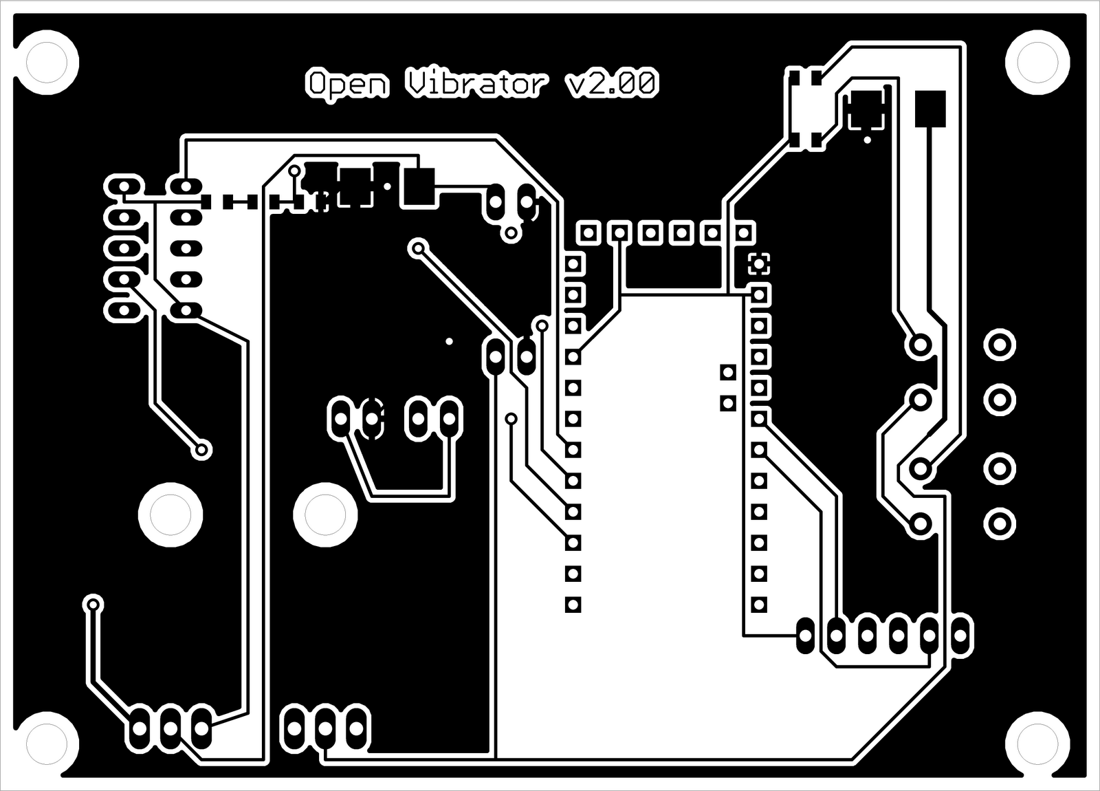
So there is still more work to do, but I think this one may be a winner.
Arclight
Subscribe to:
Posts (Atom)