Showing posts with label 3D printer. Show all posts

20141130

3D printed lock picks

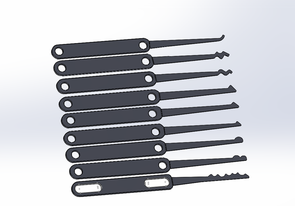
Dano was messing around the shop the other day, and came up with a really interesting concept.  He took the end of a zip tie (the part that isn't serrated), and trimmed the profile to be the shape of a lock pick.


Sure enough, it worked, but not terribly well.  I could only get a few uses out of it before the zip tie became too floppy.  The shape is easy to make, yet difficult to reproduce exactly. 

I encounter the same challenge when making metal picks.  They're easy enough to form quickly by hand, but they're impossible to duplicate precisely. When the performance of the pick is so dependent on the exact shape of the pick, consistency is king.  Also, the TSA sometimes has difficulty with metal picks in my luggage, perhaps plastic picks can solve that. 

After a few days of simmering on those thoughts, something dawned on me.  "Hey, those fancy 3d printers, I bet those could produce some awesome lock picks!"

Creating the shape was no problem, due to a quick Google search and a really neat, obscure Autotrace tool in [redacted modeling software]. 


Although Autotrace wasn't flawless, the resulting sketch was easy enough to modify to get any sharp, unusual edges out of the model.  After a quick extrusion and some geometry modification, here's the resulting 3D model


Dimensioning the part is critical, and ironically, my fancy Dimension 3D printer simply wasn't up to the task.  Southord's picks are .023" thick, which is smack dab in between the layer thickness available for the Dimension printer (with layer thicknesses of .010 or .013 and dimensional accuracy of +/- .002", typically).  Two little filaments of extruded plastic didn't seem like it would be enough for producing a pick of any significant structure, which is why I chose to make these parts on the Objet 30 Pro, with a .001" layer thickness and 600 DPI resolution (!)

My package arrived in the mail Saturday afternoon, and with a singleminded focus, I dove straight into the play locks.  Within a few moments, the good ol' Defiant lock gave up the ghost, and my compounded excitement manifested in screaming "Got it!" at the top of my lungs.


Of course, these picks were far from perfect.  Scaling was a bit of a problem, as only about half of the picks were appropriately sized to fit the locks on hand.  One neat thing about designing these digitally, is that making scaled copies is a piece of cake.  I also successfully broke two picks within 15 minutes, far from ideal. 


This exercise may seem reminiscent of trying to kill a mosquito with a cannon.  Why would I use such an expensive technology to produce a simple plastic shape?  Consider this, once I have the precise digital shape tuned, and I'm able to produce perfect copies time after time, then perfect lock picks are nearly trivial (after a little research, of course)


The next step is to try a few iterations of these picks, perhaps including some new designs, to get a kit of a dozen or so nice picks of different sizes and shapes.  Once we have that, then making an injection mold shouldn't be much more difficult.  Then we should be able to produce many perfect copies at a trivial cost.


Stay tuned for part 2!

20140427

Helping Hackers Hack Better

Work put me on a detour for first thing on Monday up in Sacramento.  That means I got to spend a random weekend visiting Noisebridge in San Francisco. 

The last time I was here (which was also the first time), I felt a familiar sense of awe, not unlike the first time I set foot at 23b.  The vibe is indescribably unique, I like the way they hack, mostly.  The one thing that gets to me more than Hacker Stackers, or an overwhelming need for consensus, was that their machine shop was looking sad for lack of love and attention.  I decided I should change that. Since this is a "Do-ocracy", I guess the job is left up to me.

A pile of 3D printers in various states of entropy at Noisebridge
The CNC mill at Noisebridge is strikingly similar to the one we have at 23b.  Both are the MaxNC model.  However, this one seems to retain the original closed-loop control, which keeps track of the position of the stepper motor's rotation.  This is to accommodate for step loss which could occur while heavily loading the spindle.  Also, it seems like the hackers here have figured out how to interface LinuxCNC with the mill, sorting out the dreaded config file to twiddle the pins on a parallel port straight into the CNC control.  An impressive feat, except, they didn't get it quite right.


Noisebridge.  See any disparity between backplot and actual cut?

23b

Without knowing, I'd guess some VERY intelligent programmers figured out the interface between machine and computer.  I couldn't reverse-engineer the pinout on the magic "black box" on my own, so I ended up tearing it off completely and replacing with a set of Gecko Drives.  What Noisebridge missed was something very elementary to a machinist, but maybe not so much for a programmer - the X and Y axis were flipped.


Hold your right hand out like this.  Your fingers point toward the + direction in each axis.  Z is usually parallel with the spindle

When I set up the machine, I expected the cutter to start nearest to the front left hand corner, which was set as my G54 origin.  But, when the mill began by traveling to the opposite side of the workpiece, I panicked and hit the emergency stop button.  "What the hell!?", I cuss as I try to sort out what's wrong.  The code checked out and backplotted fine.  Ah, I know, I've seen this before.  The world is reversed!  After a quick googling, flipping a signed digit in the config file made the control behave as expected.  CNC machines are only trustworthy when they go where you tell them to.  Otherwise, they may try to drill a hole in the table at 10,000 miles an hour.  Okay, hyperbole a little bit, but CNCs are fantastically dumb machines.  They'll happily destroy themselves, if you let them (or tell them to!)

Once all that axial confusion was straightened out, the machine happily repeated cuts for the rest of the day.  Still, the machine was VERY slow.  Since this is a tiny, bantamweight duty machine, we could never expect a whole lot in the way of high feed rates, but the 6 inches per minute that this machine was running at was excruciatingly slow.  Not entirely sure of the upper limit of the speed on this machine, I seem to remember reading somewhere that these controls barfed when they were pushed beyond 20 IPM.  Digging back in the config file, I found a MAX_VELOCITY variable that needed a  tweak.  Now set at 15 IPM (a 250% increase) max travel rate, I doubt this machine could get into a whole lot of trouble before it had a chance to prevent CNC seppuku.   


After a few confidence-inspiring test cuts, eventually the kinks got works out of the code and the machine.  Gibs were tightened, syntax was changed, and ways lubed.  The machine is now working more properly than it ever has .

traced in Solidworks, plotted in CAMWorks

 
inspired by a sticker on a nearby laptop

While this is all a bunch of fun (and also a big component of my day job), why would I spend my weekend at Noisebridge fussing around with an esoteric piece of equipment?  It's because I live for the love of hacking.  For the adventure, for the skills, for the lulz.  Also, after reading Ivan Illich's Deschooling Society recently, a point has stuck with me: I feel compelled to contribute back to the society which created me. 

Spending time at 23b and other spaces has given me a chance to shine among brilliant peers and mentors; I stand on the shoulders of giants and all the work they've done before me.  Most of these hackers, for some reason, rarely dabble in the physical realm, or if they do, it's not to the level of sophistication required to get these finicky CNC machines running under optimal conditions (does that explain the pile of non-functioning 3d printers?).  Not everyone has the technical background to get these disparate hardware, software, and artistic systems integrated well enough to do what is commanded of them, but once in a while, putting a few heads together yields impressive results.  Two half wits make a whole wit. 


You may think, "So what? G code is difficult to generate anyway!"  Yes and no.  While the method I was generating G code was from a fancy (read: expensive) software suite, it looks like LinuxCNC offers a few options to generate toolpath from a greyscale image, or from a DWG file, and a few other format types.  While there's a little bit of nuance in the code that's missing from this whole exposition, the thought is generally this: the softer the material, the easier it is to machine.  Wood machines fine under many sub-optimal conditions.  If I didn't have the spindle speed set just right, or the feed incorrect, in many materials that would break tools and scrap parts.  Here, all we wanted to do is make a silly engraving of Nyancat in wood.  There's nothing technical or tightly toleranced here where we'd have to invoke the CNC gods to get the tools to perform crazy magic.  Keep it simple, stupid.

While this little CNC isn't great for building your next AR lower receiver, it would be perfectly suited for milling circuit boards, or a custom license plate frame for grandma.  These machines are essentially useless without proper instruction, which could be a challenge at Noisebridge.  The high level required to operate the CNC keeps it more in the arcane knowledge realm.  But, now that some of the hardware and software bugs have been worked out, the machine is a little more accessible.  Baby Steps.

It's difficult to send a n00b to a CNC mill and say, "Okay, time to make good parts!".  If G-code is unintelligible to you as a programming language, then you better get help from someone before you go running a CNC.  It's not difficult at all to understand g code, especially for such a simple machine like the MaxNC.  It's simply 3d connect the dots (think LOGO, from Mr. Wizard, remember???), with about a dozen extra commands operating the spindle and other things.

In fact, 3d printers speak a dialect of G code that's not much different from CNC mills.  Perhaps the CNC mill was neglected for much of the same reasons that the 3d printers remain in disrepair - too many levels of nuanced information to synthesize in order to get the machine to cooperate using limited human resources. 


What CAN be done, though, is for me to provide more thorough documentation of setup and operation of this milling machine with my newfound knowledge, which is in the process of being updated on the Noisebridge wiki page.  That might help a few people become self-sustaining.  However, after a few successful machine shop classes at HeatSync Labs, as well as a few sessions at 23b Shop, I think it's safe to say the way to get the shop to a lower state of entropy is to bootstrap the community into activity.  Teach them just enough to be self-sufficient.  There's a few things about machining that cannot be replaced by anything except for sheer experience, but with focused training, it would be interesting to see the way the Noisebridge community could come together and solve their own problems, figure things out in their own way. 


That's a part of the hacker ethic, right? 


20131102

Where's Waldo-the-Datasheet?

Howdy gang,

Once in a while, an interesting, random project shows up at 23b's doorstep.  This week's project-du-jour is a rotary encoder / stepper motor drive.  Without getting too bogged down in the details, what we need to do here is read the position from an encoder, and then drive a stepper motor at 110% the speed of the encoder.  This is meant for pulling extruded vinyl out of a larger machine, while keeping an appropriate tension on the extrusion. 

The focus of this post isn't the extrusion puller itself, this is more about the quest I took to find out where the Mil Spec callouts were for this particular connector, so we can hook up test leads while we develop the rest of the project.

The first step was checking the product data sheet.  A "Sick Stegman DGS25 rotary encoder" yielded ample Google results, with the proper data sheet.  Cool, that was easy. 

Another bit of googling for the connector type lead me to the Digikey and Mouser website where it has the proper connector listed (I think), and it's nearly $20.  Screw that, I'll make something here at the shop (why else do we have all these tools?)  After the 3D printer was down for most of the summer due to my dumb ass putting ancient support material through the extruder, I find myself champing at the bit for every opportunity to make a customized, one off piece for any project in the general vicinity.  The printer is an incredibly useful tool, when it works. 
After examining the case a little better, there is confirmation on the physical connector that it is nearly the same part number, calling out CR3102E18-1P-1.  The numbering convention is essentially the same, but why the CR spec instead of MS? 

After a bit more smashing my face on the keyboard, I learn that the CR and MS specifications are essentially the same scheme.  CR spec came from Cannon Electronics in the 50's, and it looks like the Mil Spec connectors were developed a decade prior.  Perhaps there's some overlap?  Perhaps it's similar to the 7400 / 5400 families of ICs.

Checking Digikey for the part number, I find myself puzzled, as the part number only seems to be for the male receptacle of the plug.  What the hell is the mating part called?   After some more face-smashing and context-grokking, I find "Oh, it's a MS/CR3106-18-1, of course that was easy to figure out".  NOT!


Different Mil Spec, different connector callout.  I guess that makes sense. Now where the hell is the blueprint? 

Just looking for the -3102 or -3106 part number didn't yield anything incredibly fruitful at first.  I did find a few diagrams showing pin location, but nothing with dimensional values.  Should be no big deal, perhaps I can figure this out.  Time to break out the calipers and Solidworks. 

After getting to know my Stratasys 3D printer over the last few months, I know that it's for the most part dimensionally accurate (maybe a hair on the small side)  Sure, I could run calibrations until I'm blue in the face, but that won't help too much.  The printer operates in open loop mode, meaning that it doesn't get any positional feedback to make on-the-fly adjustments to the print head location.  Translation - even if I program something at 1.000" exactly, it may come out a tiny bit bigger (1.003") or smaller (.997"), depending on a few factors, mostly the positional tolerance of the machine itself.  I'm satisfied I can program this part to a tolerance that will be acceptable to fit.  Usually, I give loose-fitting portions a +/- .005" tolerance (depending on direction of interference).  Tight fits usually have a single sided tolerance of .002", and we have even successfully produced accurate interference fit parts. 

There's a neat feature in Solidworks where you can superimpose an image on top of your model, so you can draft features based on an imported image.  "Sketch Picture" is the command you'd use, and here's what I did.  I opened up a sketch on the back face of the nearly-finished connector plug, resized the image, and simply drafted new lines on top of the image until they matched.  Mostly.


One thing I've learned while using Solidworks over the last few years, combined on top of my experience fabricating and machining parts, is that if something doesn't look right, it probably isn't right.  With ample training, your brain can become a finely-tuned difference engine, instantly recognizing small changes in familiar objects, without needing to intellectualize what the change is.  The warning alarm becomes a subconscious manifestation screaming into your Neocortex.

These Mil Specifications are quite good about part fitment and mating.  Something immediately struck me as odd while drafting this using my image file.  According to the superimposed image, the holes aren't precisely centered on the face, nor are they parallel, or even exactly aligned with one another.  I didn't think of this as a huge problem, hoping that the generous amount of space around the pins would more than make up for any dimensional inaccuracies of my part.  Take a close look at the centerlines of the part, versus the centerlines of the circles.  It's all wonky and offset, which is what I should have expected using a JPG as a reference. 


I printed the part, eagerly burning a little bit of time for the print to complete.  After realizing I am surrounded by assholes, I returned to Mr. Printer, lovingly nestled in between Mr. Coffee and Mr. Compressor.  An excited, anticipatory removal from the machine only led to my disappointment.  In this case, close enough wasn't going to cut it.  The pins were offset too far, something was wrong with my design. 

Shit, it doesn't fit all the way

Dammit.  

you can see a few of the pins barely peeking out

Back to the good ol' drawing board.

So what went wrong?  A quick glance down the holes, and you can see that the pin spacing wasn't quite accurate enough to get us a decent fitment: the plug is jamming on the pin diameter.  Since I gave up on finding the exact dimensions early on, looks like I'll have to dig around on the internet to find the exact specifications for this particular connector.  More Googling. 

As it turns out, there isn't any one specific drawing on the 3106 connector.  Rather, it lives as a subset of the byzantine MIL-STD-1651,where there's a breakdown of all variety of round connectors.  266 pages of connectors, not ordered in any specific way.  Even when searching for the term "18-1", I got close, but not close enough.  Turns out, the X in 18-X gives a variation on the part, usually a rotational value for the pins, and there's umpteen different varieties of rotation, and not even with the same pin population!  


DAMMIT, this last one is close, but rotated 90* off. 

FINALLY, after manually scanning each page of the document (really only about 20 minutes of work), I found the correct specification. 


Strange, even though the pin population is the same as the last spec (18-24), the spacing is just off enough where it wouldn't match, even with a rotation.  Time to update the model with the correct information. 


how about a googly eyed connector?

Close wasn't close enough.  The change in hole location seems to reflect the skew in my first part.  My brain processed the resulting linear offset accurately without needing a measurement.  Now if only my brain could be calibrated for more useful things, like where I leave my keys every day...

A quick revision to the hole locations, and off to the printer.  But wait, things can't be that easy, can they?  Of course not. 

One of the complications I've run across with the 3D printer is incomplete layer slicing. 

Just like reading toolpaths for CNC machines, when slicing a 3D model in Catalyst, it gives a preview of the toolpath before the print, which provides a quick and robust method to diagnose the print quality before finding out the hard way.  Look for erratic motions in the toolpath, or strange insertions of support material.  In this case, we saw both. 

STL file imported into Catalyst

The red lines indicate model material, and the white lines indicate soluble support, typically inserted if there are any overhangs to the model, building up a support network from the bottom up.  Since there weren't any programmed overhangs, why is there support here?

After slicing.  Notice the support material in the middle of the part.  This is bad, something is wrong.
Top view of the same part.  What's with the hole contours? 

Checking out the top view of the toolpath, you can see how some of the holes are artifacted and incongruous with the contours we programmed in Solidworks.  What happened? 

My first clue is the hole size, and the spacing that requires.  These features are getting pretty small, and the spacing between the holes is getting thinner and thinner.  Even though the finest level of print is .010" layers, that doesn't mean that the plastic extrusion is exactly that size.  The extrusion head prints layers that are substantially thicker than they are tall, nearly .020" wide.  This can cause problems for interpreting smaller dimensions, as well as the fill pattern between thin walls.  In this case, Catalyst changed the programmed contours of the circles to now have a bit of cutaway, probably to accommodate for the XY size of the extruded plastic.  While these changes would be minute, since we're dealing with small parts and tight tolerances in the first place, allowing these changes to be made by Catalyst would at best produce a part that doesn't fit correctly.  At worst, it may have messed up the entire print by inserting support material where none is intended - I've even seen whole layers of support inserted in the middle of a print, effectively ruining the model half-way through.

After a few revisions to the part (making the hole size slightly smaller, so the wall thickness can be larger), I was able to find some dimensional values that would happily process in Catalyst.


Much better, Aziz

Notice the holes look right, now?


 So how did the part turn out, after all this trouble?  Perfectly. 


This is a much more satisfying result.  The printed parts fit precisely, as long as they were designed precisely.  Not everything works on the first shot, but success the second time around isn't a bad consolation prize.