20100818

Droid camera + low light = scary shop night scene


I've discovered that the welding booth lights, microscope, and a few other small light sources can turn the shop into a nice, cave-like environment for coding or studying or whatever.

Here are a couple of scary pictures I got with the 5mp camera on my Droid phone.


Welding booth (red UV curtains):

It seems like the less light you have, the more bizarrely these little camera react.

Now I'll have to get the tripod out and see what happens when there's no shake, and the flash is disabled.

20100816

Electro Etch is GO


This article describes my homebuilt AC/DC electro etching device. It's built from plans I got online -- I got the original plans from http://www.knives.mlogiudice.com/knifeshop/etcher/index.shtml . During the design phase, this site was the most helpful for the hardware building. I now know I can go ahead and use any basic power supply design pretty easily, so the next one will surely be a circuit of my own design.

The etcher is mounted in an aluminum case salvaged from a parallel printer sharing switch from the 1980s.

This is the second build of this circuit that I have done. This one has a much better case and a larger capacity transformer than the first, but the components are all salvaged from the first build except for the case and transformer. Total cost was <$30 -- it's only that high because I bought almost everything new the first time around. Just about any power supply will do -- I have used a wall wart transformer with the plug cut off and a couple of alligator clips soldered on to do etching and plating. Stick to lower voltages like 6-24v for sharper results, since the image tends to bloom with higher voltage for longer time. Make sure you get the biggest current rated tramsformer you can, since this circuit can easily put out over 1000 mA of current through your workpiece and a smaller transformer will definitely overheat or short out in an exciting manner. I would recommend looking for at least 1 amp output to avoid overheating.

BUILD IT:
The plans at http://www.knives.mlogiudice.com/knifeshop/etcher/index.shtml are abundant with parts list, schematic, etc.

Here's a link direct to the schematic: http://www.knives.mlogiudice.com/knifeshop/etcher/electro-etcher_circuit.pdf

FIRST POWERUP:

Safety glasses on! The first time you start the circuit you risk finding accidental short circuits and bad solder joints, defective components, etc. Please protect your precious eyes so you can keep having fun.

Use your hand (or go to Harbor Freight for a $10 IR thermometer, for safety) to check how warm your components are when you power up for the first time. Check every few minutes on the heat level of the transformer, bridge rectifier, and other heat-generating power components. After it's running stable, you can thus be confident that your circuit runs in a known manner.

STENCILS:

For stencils I have used all different things like electrical tape and contact paper; anything electrically insulative will work. Draw your design with a Sharpie or paint pen (or a graphite pencil) and cut ewith a utility or craft knife. You can also cut with stencils or punches; I used a tiny round punch to make dot matrix letters and it worked fine.
You can even paint on the surface or use asphaltum, wax, or almost anything resistive. See a printmaking book for further suggestions.

Currently I have stencil paper that starts out completely insulative, but turns conductive where it's written, typed, or stamped. It's a fine plastic mesh ribbon with blue waxy emulsion which you push out when you impress the ribbon. Thanks to a friend with contacts in the marking industry, I got this for free because they ordered the wrong material.

You can get (or better, make) steel stamps made of your logo or words, for stamping straight onto the stencil paper. The mint box was done this way, using a CNC milled 23b Shop logo as the stamp. (I actually burnished it with the flat of a Sharpie; I didn't stamp it because it is a large and thin milling.)

The stamp doesn't need to be hardened like a metal-marking stamp does, since you are just stamping the paper on a soft wood or plastic surface -- you can use wood or plastic for this kind of stamp, or a piece of softer metal like copper. You could even electro-etch a plate and burnish it into the stencil paper.

Note that a greater exposed surface area of your stencil will mean a slower etch. Same with a larger probe.

ELECTROLYTE:
Storebought electrolyte solution is probably more effective, but I have table salt and baking soda to work with at the moment, and they both provide good results.

Starting with oil-free metal is a must. Otherwise the oil will insulate parts of your design and ruin the line quality. This means scrub with #0000 steel wool and a bit of dish soap, or use another degreaser of your choice. You can sandblast it as well -- this removes the oil plus a bit of metal, leaving a satiny finish to contrast the smooth melty appearance of electroetching.

Salt water electrolyte rusts metal very quickly, so rinse and brush finished work well and dry thoroughly with forced air, a warm sunny spot, or a heat gun or hair dryer. Apply oil or WD-40 right away.

MAKING PROBES:

You can probably use any fabric to protect the probe surface from direct contact. I've used t-shirt fabric and synthetic felt to good effect.

I have made several probes
with stainless welding rod for the conductor and brazing or welding a banana clip lead on, then sliding into a plastic hollow rod for a handle and taping, wedging, or gluing it in place. Favorite shape so far is a hockey stick with about a 3 inch exposed conductor, bent at 60 degrees or so, 1 inch down from the plastic handle. This allows wiping across a roughly 2" swath, or leaving it in place to etch a small design.

I also made a probe from a circle of heavy stainless screen, a few layers of t-shirt material, and a 4" PVC pipe cap. It's used for longer duration etches, flat plates, and larger designs. Wired it all together with a bit of stainless wire and clipped a banana jack into the inside. I can set the probe on a workpiece with the pad downward, and pour electrolyte into the cup shape. This trickles through and collects in a plastic dripcatcher pan, so the electrolyte stays really fresh and the current stays high. It can then be recycled until the current drops too low. This design is win.


A spot probe with a stainless mesh and a felt pad, all on the end of a 3/4" or 1" plastic dowel, will come next.


HOOKING UP THE PROBES:

The workpiece is attached to the positive terminal with a spring clip or wire hook. Stainless steel or titanium are best if the piece is to be immersed in electrolyte. No copper should be exposed to the electrolyte anywhere, or else you risk polluting your solution and plating your workpiece or probe.

The probe is at a negative voltage to the workpiece during DC operation -- so clip the probe on the negative or ground of your output terminals, and the workpiece to the +12 or +5 side. The metal from the workpiece migrates toward the negative terminal, is my understanding.

Avoid touching the probe's metal to the workpiece directly; this maximizes current and minimizes electro-etching action, heating your circuit and possibly shorting components.


You can clean the probe off when it gets gunked up by reversing the voltage and DC-etching the probe; the cruft will collect on your sacrificial workpiece. This is also the basis of a larger electrical de-ruster; plans and pics of our 35 gallon de-rusting device to follow.

FUTURE PLANS FOR THIS PROJECT:
I am going to be adding a voltmeter / milliammeter to avoid having DMMs clipped in all over the place, but it runs stable and cool at 10.5VDC out sending about 500mA through the circuit.

Also making more smaller spot probes would be nice, for doing a small touchmark or logo on a tool or knife handle.

I'll be soldering the whole thing permanently together and removing most or all of the spade connectors.

awesome workbench!

Today's workbench of renown is at Willie's Shoes in L.A.
Check the video and enjoy a lot of really amazing old leatherworking tools, amazing historical photos of celebs who've gotten shoes from Willie, and some very nice industrial sewing machines. These tools are old and worn, but they allow craftsmen to create beautiful, useful, and satisfying work because they're just right.

http://vimeo.com/11075261

20100810

Making PCBs at home - Part 2


The quest for the perfect "fab at home" PCB solution continues. This week, we started playing around with "Direct PCB Printing" for making printed circuit boards (PCBs).

First, here is a quick recap on how to make PCBs at home.

To start with off, you need a layout. I'm currently designing the schematic and PCB layout with Eagle Cad and either outputting image files in monochrome or printing directly from the program. Exporting the images has the advantage that I can put multiple PCBs onto one board or page to save materials. Printing directly from the program is simpler.

Once I have the artwork, I fab the board and drill using a Dremel-brand micro drill press and carbide PCB drills. We buy resharpened carbide PCB drills on eBay. Common sizes are #52-#70. For best results, get a pair of dial calipers and mic the pins on any through-hole components you will be using.

For the fab part, there are basically 3 methods that are practical to do at home:


1. Photo resist:
Laser or inkjet print to transparency paper, expose your image onto a pre-sensitized PCB board (you generally buy them this way), develop, etch. You can buy these from Mouser, Digikey, or your local electronics store.

Advantages: Tried and true method, good resolution.
Disadvantges: Messy, need glass exposure frame and bright sun or a UV light, extra chemicals involved. Double-sided boards are possible but you need to line the images up carefully before exposure.

2. Toner transfer:
Laser print or photocopy your image to Press-n-peel or specific types of glossy paper stock, then iron the image on to your bare copper PCB. Any PCB stock will do, but it must be cleaned with sandpaper and degreased with acetone before applying the transfer. Remove the paper by
soaking in water, tocuh up any bare spots, etch. Works best if you use a laminator or a very hot iron.

Advantages: Cheap, easy, moderate resolution. No chemical needed other than etching solution. Double-sided is easy - you can drill some of the holes after you transfer the pattern for the first side, making it super easy to line up the second side artwork on a light table.

Disadvantages: Can leave pinholes or bare spots that need touching up, paper can be hard to remove. A new 2-step kit called "Fab-in-a-Box" is supposed to address this. I just ordered it, so I will let y'all know how it works when I'm done testing. Works best with medium sized (i.e. 16mil+) traces.


3. Inkjet PCB printing:

This is the new up-and-comer. The basic process involves either printing
on a modified Epson inkjet, or using a stock model that accepts CD-ROMs
and a special adapter. You clean the board like you would for toner
transfer, load it into the printer, and let it do it's thing.

A special refill ink called "MIS PRO Yellow" is typically loaded in
one of those aftermarket refill cartridges. Once printed, the board
is "cured" by heating the ink on a hot plate, and, depending on the
results you are getting, sometimes a second coat is printed and cured.
Etching is the same as above.

In another variation, some toner or powder-coat is dusted onto the wet ink
before cooking. This results in a very strong coating with one pass.

Advantages: Amazing resolution. 8mil traces are possible, although I've
only done 10mil so far. Clean and neat, and misprinted or smudged boards
can be re-used by wiping off the ink with acetone.

Disadvantages: Can only print specific sizes (the adapter I have in mine
does 3.5x2.5" boards at 1/32" thick). Larger boards require modifying the
printer extensively, and attaching a tape leader to feed the board.
Process is a little fiddly and you have to play with the margins, ink
settings, etc for good results.


So far, the results are promising. We bought the kit from Full Spectrum Engineering and then set about finding a suitable inkjet printer. Fortunately for us, there is a Goodwill Industries computer center nearby. For $15, I picked up an Epson R200. This printer has two properties that we need:

1. It accepts CD-ROMs (the boards we use fit into a CD tray adapter)
2. It has an piezo-electric print head that will run a variety of inks.

Ours was missing the CD tray, but it turns out that these are available all day on eBay for around $10. Next, we needed a blank ink cartridge and a bottle of Yellow MIS-PRO ink. We also needed a way to reset the empty cartridges so that the printer will actually try to print.

For about $30, we found all of the necessary supplies at Ink Supply, including a chip resetter tool, a self-resetting empty cartridge, and the ink.

After lining up the adapter in the tray and taping it on, cleaning the 2.5x2.5" PCB blanks with 320 grit sandpaper and acetone, we ran some boards. The first one was less than spectacular, as I failed to read the directions and only ran one coat, then failed to cure at a high enough temperature. The best result (board #4) was obtained by running a pass of MIS-Pro ink, then dusting with power coat powder and heat curing. This created a very solid resist with clearly visible 10mil traces. Photo is below:


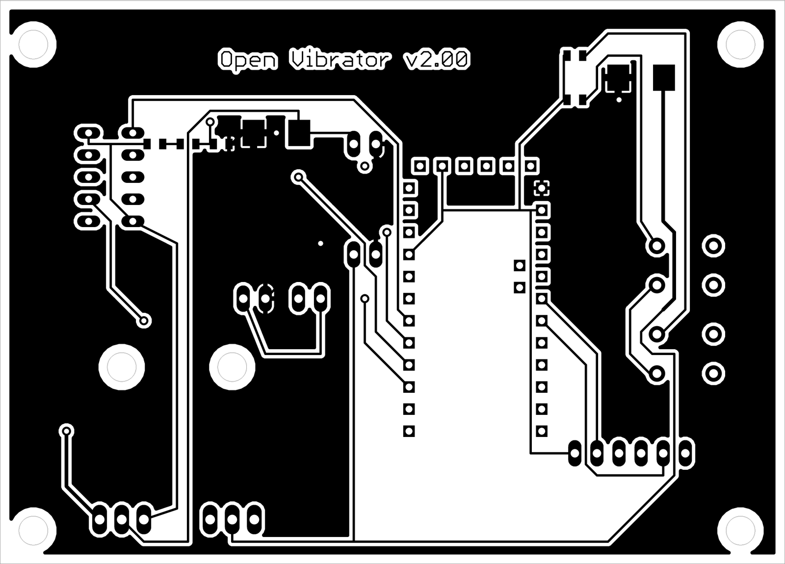
And here is the original art work:


So there is still more work to do, but I think this one may be a winner.

Arclight