20151202

Computer Aided Design for the modern world - meet Onshape

Muggles generally don't use CAD software because the good stuff is expensive, and the free stuff sucks.  No matter what, it's always a pain to learn to use, and rarely geared toward more casual use.  You get what you pay for, information doesn't want to be free.  

"THAT'S never happened to ME before"

Last March, after spending nearly every waking moment of the previous three months at my tech support job un-fuckleing people's D.I.Y. Solidworks installs, I ran across something on the 'net that exploded my head. 

Professional grade CAD on the cloud.  For free.  Onshape


I know what you're thinking, "There's no such thing as a free lunch!  There is no such thing as the cloud, it's just someone else's computer..."  But that's just it.  Virtualization is exactly what the CAD industry needs. 

You see, Solidworks, just like every other big piece of software, is a jealous stampy elephant. "That elephant cost me thousands of dollars!"  How right you are, Homer.  This is a great clip, you'll know of my my plight immediately.  "And now I'll get my hands out with my face." 


Professional CAD software is capable of doing a great amount of work commanded by a skilled mahout, but be very cautious during musth season.  For Solidworks, typically 90 minute long, 5 GB installs of byzantine configs and unknowable dependencies can make for a lot of headache during software upgrade season for those experienced with the process.  Now imagine what happens when every Barney Fife in the engineering department takes a stab at the same software update on their own?  *shudder*

The problem is, Solidworks essentially forces everyone to upgrade at the same time, since new files aren't very backwards compatible with old versions.  If your customer sends you a part file in 2016 format and you're still on 2014, you're faced with a nontrivial maintenance fee if you want to ever see your customer's files (thanks for changing the policy this year, D'assault!).  With Onshape, you're always on the latest greatest version, no matter what. 

We all have our own tech support horror stories, so I won't bore you with mine other than it saddens me to consider how much of my life has been spent watching status bars slowly creep across a screen. 

My biggest complaint has been the physical size of the hardware.  Yes, we've come a long way since the days of PDP-8, I should be grateful for the 15 lb monster of a workstation laptop I dragged around.  When nVidia mailed a Grid Server to my office a few years ago, I couldn't be more excited.  "Wow, now I can do my CAD on a thin client!".

I never got to use the damn thing, the project was canceled only a few months in.  It would have made one helluva bitcoin miner.

During my travels to San Francisco this past April, I made my pilgrimage to the infamous Noisebridge Hackerspace to teach a CNC machining class.  Their machine is pretty much what got me started down this crazy hacker journey a few years ago.

While visiting, I was showing off Onshape to one of the local denizens.  "Oh wow, it works on ChromeOS," he remarked.  I didn't notice at first the Chrome terminal I was using for Onshape.  That's when it all hit me.  "Why in the world am I carrying around this Death Star laptop when all I need is a connection to the internet?"

I totally understand that Computer Aided Design is number-intensive, requiring unobtanium graphics cards that are optimized for doublelong precision numbers so your designs remain accurate to half a wavelength of ultraviolet.  I don't  understand needing two hard drives in a laptop anymore, like my workstation came equipped with.  When you think about it, though, most of the machine is pretty much unnecessary at this point in history, if you've got enough AWS space to throw at it.

"But the cloud could go down", or, "I want all my data to be mine, private and nobody else's."  Yes, that's one small price to pay for this awesome "freemium" tool.  You're not Boeing, you don't need 100% uptime, iron-clad data control for your trinkets.  If you do, Onshape offers services just for that. 

"Back in my day, I had to scrimshaw custom ring tones in raw MIDI, and I was happy about it!"

 We simply don't live in those dark days anymore. 

After a few years as a professional Solidworks user, I find that Onshape meets most of my needs about 80% of the time with 80%  the package (subjetive, i know).  I also feel that at least 80% of the basic skillset between Solidworks and Onshape transpose, even some of the hot keys are the same (that's more objective).  Here's an interesting fact, the founder of Onshape, JON HIRSCHTICK, is also the founder of Solidworks, which he funded with his earnings from his time on the MIT blackjack team.

Don't get me wrong, Solidworks is a great program, there's a reason it's a de facto industry standard.  What I'm saying is that maybe you don't need the ultradeluxe simulation package if all you need to do is make some trinkets for your mom on your Makerbot.  The nice thing about using Onshape is that when you're ready for more, you can go straight to using Solidworks with a existing skillset.

Working in the machine shop, my job is to make shapes defined by their size and dimensions.  "I need a half inch thick gasket three inches around with four quarter inch bolt holes evenly spaced around the perimeter"

Here's your gasket, maybe you'd like to describe it more fully, there's some dangling dimensions
 
 That's why I think the 3d printer is so nifty, it trivializes what used to be a long arduous process to make a complex shape.  The 3d printer can easily produce shapes that traditional processes can't begin to touch. 


Powerful CAD is the only way to interact with 3D printers, unless you like scrimshawing megabytes of raw G code. 

If low level is your thing, there's always OpenSCAD.  See that script on the left side, that's how you program in OpenSCAD.  Not graphically, in raw code.  No thanks.  Nope.


While writing this blog, I grabbed a random complex model from GrabCad, in this case a 3D printer assembly, in a neutral file format, and imported the same file both into Solidworks and Onshape.  Onshape cleverly integrates a file management system, with many models already uploaded and available for everyone to integrate in their designs.  For this test, I used a file from another source, in a non-native format.

In a dramatic show of mettle, I raced the two side by side, and even let Solidworks have a head start on rendering the file while the same one uploaded (200+ MB) to Onshape.  This is the result. 


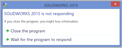
After 30 minutes of waiting, Solidworks still could not render the file.  I'll be honest and say I'm not using an Solidworks-approved graphics card, but isn't that type of problem what we're trying to move away from?   I'm pretty sure that Sketchup, TinkerCAD, etc., would also fall flat on their respective faces, assuming they can handle STEP files at all. 

When Solidworks crashes, it can be catastrophic.  Your data is lost, your setting are buggered, hours of work vaporized.  At the very least, you probably have to restart the program, or reboot your computer.

With Onshape, if EVERYTHING goes wrong, all you do is reload the browser window.  After about 40 hours of solid use, I have yet to run Onshape so hard into a wall that it seemed unstable in any way.  I'm sure if I tried hard enough, I could DDOS myself by dividing by zero in a variable somewhere, but truthfully it's an amazingly robust program.  When you make an error that would cause Solidworks to puke buffer overflow all over itself, Onshape politely stutters, and simply refuses to render the last command (consistent architecture on the cloud is a bit more predictable?).

These are using the same data, Onshape on the left, Solidworks on the right.

Your 3D printer is useful for so much more than printing Yoda heads you downloaded from Thingiverse.   Combine the printer with some baseline 3D CAD skills, and suddenly your lowly Bukobot is a much more capable machine.  If you have a little bit of motivation to learn modern, powerful CAD like Onshape, then your only limitation is your imagination and patience.  Plus, you get a neat transposing skill set, having basic Solidworks skills without the Solidworks price tag.

evolution of a combat robot

As with any piece of software, there's still a bit of a learning curve involved.  Luckily, there's THOUSANDS of Solidworks users sprinkled throughout the world who can give cursory advice, lots of resources available online to learn the software, and we're starting to see Onshape classes being offered at hackerspaces around Southern California.  It's mostly a matter of getting out there and using it. Everyone has stuff they want to 3D print, this is one more excuse to make the cool things you've always dreamed of. 

Have you ever struggled with needing a part of a specific size and shape, that doesn't exist anywhere in the world?  Using your 3D printer, along with Onshape, can easily solve those problems which has haunted many nearly-finished projects that only needed a simple PCB standoff with offset holes.  Onshape isn't perfect, nothing is (what IS perfect?), but it's a great way to get your feet wet with industrial-grade 3D modeling software without getting hosed.


20150830

n00b hacks harder

This is Tim:


Tim's only somewhat a n00b.  Tim is an electronics expert, and music hacker; so much so, he created a synthesizer for the Nintendo DS.  Sometimes he just needs a little help with the hardware. 


Tim sometimes needs help with his hardware hacking game, to build electronics enclosures and stage accessories for his performances.  Tim frequently visits 23b Shop, Mag Labs, and Null Space Labs to do just that.  Clearly a hackerspace connoisseur.


Tim uses his product to perform live chiptune compositions, you may remember one such performance from Sparklecon.

https://vimeo.com/85220180


Here's a sample of some of Tim's trial-by-fire exploits. 


Tim has even gone through the trouble to learn Solidworks to up his game. The process was non-trivial and sometimes painful, but it paid off with awesome looking results.


Recently, Tim asked for advice on how to hack is new things.  "Maybe I can use the CNC mill to make the holes in this enclosure?"  


The Bridge Troll scoffed, "You've only got a dozen holes!  Carefully measure and lay out the panel, and drill away at home!  You don't need us to do this child's job!"

 CNC milling can be a challenging option, and certainly not one for the inexperienced.  CNC is a great option when you're making many copies of the same thing, or if something needs to be quite precise.  This is a box with some holes for big knobs, it probably doesn't need to be engineered to aircraft-grade standards.  "Go drill that on your drill press, and stop bothering me," I think to myself. 

Turns out, the Dunning-Kruger effect also works in reverse.  "Their research also suggests that conversely, highly skilled individuals may underestimate their relative competence, erroneously assuming that tasks that are easy for them also are easy for others."

Oops.


 "I started off taping the design to the box so that all of the holes would be properly lined up. Then I used a punch to make sure every hole had a proper center point."  Too bad we didn't think to mention a center point doesn't do much good without a subsequent center drill (before the real drill)

"Some of the holes could be made on the drill press, but because of the side of the part and the bends in it, some of them had to be done "freehand". That's what really gets me into trouble!"  NO, DON'T DO IT, TIM!!!

"Even stuff I drilled with the drill press was not immune to wandering, somehow."

 
As I begin to sarcastically joke, "I remember MY first time drilling thin aluminum," it dawns on me that it wasn't so long ago that it was in fact my first time drilling holes in thin aluminum, and they looked every bit as gnawed and chewed by robotic zombie rodents. 

Unfortunately, the diagnosis for recovery on this part was not good.  It's much more difficult to put metal back on than it is to take off, and the top half of this enclosure seemed beyond salvation. 

Undeterred by so much tilting at windmills, Tim came back to the shop last night with a flat, laser-cut panel of acrylic, determined to replace the now-scrapped curved top by bending a new one. 

"Roh'kay Raggy" my inner Scooby-Doo taunts from just beneath my conscious level.   Let me guide you, Tim. 

We improvised a bending jig by comparing the scrapped top panel to some pieces of wood and bar stock we had laying around the shop.


Getting ready to bend, I ask Tim, "Do you have any pieces to practice on?"

"No..."

"Allow me to get you something to practice on first, before we scrap the one good part you have."  Good lesson to learn right here, if you're going to make one single piece, you might as well make three, because you're going to scrap two in the process.


Turns out propane was a little too aggressive


Aaah, much better with the Harbor Freight heat gun. 

Bend one went well.


Another one of those voices bubbled up from my subconscious once again. 

"Did you consider a bend allowance?"

"What's a bend allowance?"

*Sigh*


When you make a bend in material, a portion of the material on the outer edge of the bend is stretched around the bend, while the material on the inner edge is compressed. 

When this happens, the material deforms, stretches, and shrinks in predictable ways, based on the magical "K factor" of the material.  Copypasta for clarity -

"K-factor is a ratio of location of the neutral line to the material thickness as defined by t/T where t = location of the neutral line and T = material thickness. The K-Factor formulation does not take the forming stresses into account but is simply a geometric calculation of the location of the neutral line after the forces are applied and is thus the roll-up of all the unknown (error) factors for a given setup. The K-factor depends on many factors including the material, the type of bending operation (coining, bottoming, air-bending, etc.) the tools, etc. and is typically between 0.3 to 0.5."


Fortunately for Tim, without knowing the K factor (or needing to know, for that matter), his bends were PERFECT. 

Unfortunately for Tim, he didn't account for the bend allowance, making his part a little bit short across the top.  He made the executive decision to cut a slit down the top of the part, and will patch it later with another flat piece of acrylic bonded to the top.  "It's not a bug, it's a feature!"

Nice save, and a VAST improvement from his first attempt a week or so ago. 


Well done, Tim. 

20150512

Today's knots

I tied a few Turks Head knots for some knot tool handles today.

These were all tied on a plain old wooden mandrel without a diagram, pattern, or other visual aid, just following the rules of the knots to make them right.


I used 2 or 3 tightening passes to dress the knots, which are tied with thin seine twine of both tarred and untarred nylon. Super durable, and it looks better with age and patina.

The pineapple knot on the right is 1 inch in diameter. I tied a black Turks head with 8 bights and 9 parts.  Its pattern is Over 1, Under 1.
Then I tied a white Turks head knot with 8 bights and 7 parts intermingled through that knot, with pattern Over 2 Under 2.

The thin black knot is a 13 bight Spanish ring knot raised from a 3P Turks head.
It has an Over 2 Under 2 pattern.

The big white TH has 8B 7P, in an O2U2 pattern, and is doubled the easy way; I tied it with a doubled strand and was careful not to twist it, as opposed to using one strand and following the knot around twice, which is the more frequently used method of doubling a knot. Either way you do it, the finished product is practically the same, but with the easy way the tightening is quicker and better suited to production work. You can use multiple colors either way.

20150227

3D scanning, on the cheap

I have this friend, Mr. Bot, he always has some cool magic trick up his sleeve.  Sometimes, it's sabering the tops off of wine bottles with a wine glass.  Sometimes, it's a mobile pool in the back of his Toyota truck.  This time, it was a brand new Microsoft Kinect. 

"What's that for?" I asked him. 

"3D selfies" 


My curiosity had been piqued. 


After a half hour of downloading, installing, and fiddling around on the shop computer, the system was finally set up properly.  Some troublesome googling yielded the correct Kinect SDK, and the black box Kinect was now ready to grok all the 3D information put in front of it. 

Showing me how to use the system, Bot poked around at some scan settings, sat down in front of the sensor on a swiveling chair, and spun himself around slowly so Skanect could build a 3D model.  This is accomplished by sampling many single sided depth maps and stitching the result together (which is why it's important to set preferences in the beginning, determining the depth of field to scan).

Before configuring the system thoroughly, Skanect was able to sample at 3-5 frames per second, requiring us to swivel on the chair at about 1 RPM.  This low sample rate is due to a few variables, primarily having a misconfigured graphics card.  I'm using a nice PowerColor ATI card (thanks CharlieX), but it seems that Skanect prefers the Nvidia family of cards to take advantage of their CUDA drivers.  My machine ran fine without the precisely specified card.   I've heard of Skanect running on a real flame-throwing computer at nearly 30 FPS, allowing the system to record detailed depth information in nearly real-time, and also mapped in full color!


Regardless of a little bit of lag, the Skanect software performed admirably.  One challenge with 3D models (and the resulting STL file) is continuity of surfaces.  Since STLs (and the raw data coming in from Skanect) consists soley of a very large point cloud, you can imagine that there's a few vertices which are malformed or unconnected.  Unconnected vertices pose a problem for 3D slicing programs, when the program is tracing the perimeter of a slice and suddenly sees a small but disconnected vertex, the slicing program usually vomits all over itself and forces you to tweak your model ever so slightly, which is usually a big pain when you have a million-plus vertices to inspect.  Not with Skanect, though.

Skanect has a few tools built into the software to prepare the model for printing.  In addition to unconnected vertex problems on the model, the depth of the resulting surface is also an important consideration.  3D modeling programs are quite picky about whether your model is either a surface (with no volume), or a solid model (with volume).  Depending on how you move around the scanner (you can also move the scanner around you) will determine whether the resulting model has a continuous surface, or it may miss some geometry at the top of your head, leaving you with a big gaping hole at the top of the model.  The "hole in the head" jokes get tiresome quickly, so be prepared.


Here's those "disconnected vertices" that can cause hell for your slicing program.  Luckily, Skanect contains some handy tools to solve those problems for you.  There's a "Watertight" command available which auto-magically fills in any gaps on the model, eliminating some of those missing, floating, enigmatic vertices. 

If you're using the demoware version of the software, you're limited to outputting models with 5000 faces.  That may be enough resolution for you, and it also keeps the files down to a manageable size.  Should you decide to spring for the paid version ($150) of the software, you can now save a much more complex model, sometimes surpassing a million vertices.

5000 polygons
1 Million Polygons

Striking resemblance, no?

It's hard to see in the image, but the sensor was even able to detect the fuzzy texture of my sweater that day.  The brown you see is undissolved support material (I was in a hurry to see this, and didn't wait around for the cleaning tank to finish).  The above model was well over a million vertices, and the file ended up being about 100 MB.  I never cease to be impressed with the fine rendering of organic curves by my Stratasys 3D printer.


Depending on how much of a graphics oriented computer you're using, and how well developed the slicing software is, that can put an unruly load on your computer.  Skanect also allows you to simplify the model to any number of target vertices you specify.  There's definitely a fine balance to be struck between resolution and file size.  One useful target is <25,000 faces, under which you can easily import the shapes into Solidworks, for more powerful 3D manipulation. 


For those of us on a budget, there's always MeshLab

An interesting command to know in MeshLab to change the face count of your model is "Quadratic Edge Collapse Decimation".  This command allows you to simplify your mesh to a target number of faces.  You lose some resolution in this process, but also may lose the unwieldiness of a humongous file.  This allows you to reduce the resolution on a model to the point that you end up looking like Max Headroom, glitches and all.


MeshLab also has some limitations for opening unwieldy files, so keep that in mind when you initially export the model from Skanect.  I've found it's easier to reduce the size of the file when initially processing the scan, rather than upon exporting the STL. 

Come by the shop sometime for a 3D printed selfie.  In the meantime, stay tuned to part 2 when we test the dimensional accuracy of the scanner against known references.

Bonus: if you're an LA / OC local, the Long Beach Public Library has a free 3D printing studio open during the week.  I HIGHLY recommend that you swing by and check it out, that's where I made the green print above.  The entire process from scan to print to walking out the door took about an hour.  They also have a seat of Solidworks on a public computer there (!), as well as some other powerful photo and video editing software.  It's a great way to get started with the scanning / printing process without spending a single dollar. 

20150223

Angry Electric Pickle

Years ago, my dad pulled off a memorable trick for a Halloween party.  He cut an extension cord in half and stripped the wires back a bit.  After connecting the hot and neutral wires to dinner forks ("What's he doing?" I thought), he set up an electrically isolated jig to hold a pickle which is now impaled on either end of said forks. Plugging the extension cord into the wall gave us a 120 volt pickle-colored light show, something like this one. 


Okay, maybe our light show that evening was not quite that scale, but you get the idea.  The yellow-green glow is actually the spectral emission of sodium, through a pickle filter.  (Would this be called an Organic Light-Emitting Diode?)  Think of the color of the Sodium lights we all know from streetlights.

One of the perks of hackerspace patronage is that you get access to things like bigger and better power supplies, and you can use those tools to facilitate thinking "out of the box".  

There is a 15KV neon sign transformer sitting on the back bench, but after some consideration, I worried about the pickle lasing onto my bare retinas, or emitting energetic x-rays if I used the wrong thoriated tungsten electrodes.  I wondered if I was thinking in the wrong direction. 

"Hey, that big TIG/Arc welder in the back is essentially a big low-voltage transformer that can handle a lot of abuse..." 

A few months ago, me and Harald were trying to solve a problem.  We had a hundred or so lengths of 3/4" mild steel bar that needed to have 90* bends in them.  There were too many bars for the amount of acetylene that remained squirreled away in the tanks, so we had to consider a heat source other than oxyfuel.  In his stereotypically overbuilt fashion, Harald remarked, "Maybe we could use carbon gouging rods" 

Carbon's melting point is roughly 6500F, it can surely handle the amount of heat from the torrent of electrons flowing through an arc.  Using a single electrode attached to a welding stinger, you can generate a powerful enough stream of electrons and photons to cut through thick chunks of steel.    Carbon electrodes are also used in electric arc furnaces, the heart of most modern foundries.  Giant electrodes flow tens of thousands of amps to melt large cauldrons of steel and aluminum.  Serious heat generating capability, for sure. 


So what happens, we thought, when we connect two of these electrodes together?  Better yet, who remembers the inanimate carbon rod that saved Homer Simpson and all those astronauts many years ago?  The inanimate carbon rod was also given the "Worker of the Week Award" in recognition of his long overlooked "tireless efforts" which the plant could not function without, earning a managerial position above Homer.  Heh heh heh. 
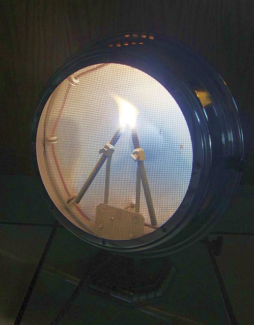
Have you ever seen a carbon arc lamp attached to a searchlight?  That's the type of brilliant photonic emission we're talking about.  Pure bright white light from a large electric arc between two carbon electrodes.  For a second, consider the vast amount of visible light emitting from this beam.  There's also a healthy amount of infrared photons, which is far easier to detect when you're up close and personal.


Harald and I put on our P.P.E. (safety third), connect the electrodes, flip the welder into AC mode, and strike an arc between the carbon rods. It took a moment to get the hang of scratch starting them together, and getting the arc gap set just right between my hands.  Playing around with the gap and the orientation of the electrodes allowed us to controlthe shape and the brilliance of the arc. 

We could only do this for about 30 seconds at a time before the residual oil on the backs of the welding gloves started to vaporize from the sheer intensity of infrared radiation of the arc.  Even after wrapping our gloves in aluminum tape, the heat was still too intense to bear for more than a brief moment.

I'll never forget the neighbor's surprise.  He saw our silhouettes outlined on the opposing building's wall and came over to find out WTF we were up to.  "I was wondering what you guys were doing" he remarked with a chuckle.

Harald and I wound up cold-working the steel bars.  Give me a lever long enough and a fulcrum on which to place it, and I shall move the world.

Problem solved, but now we have a bunch of useless carbon gouging rods. 

Or are they....

The arc welder and accoutrements are rolled out into the parking lot, along with the beefiest extension cord known to man.  A makeshift pickle jig is hastily cobbled together from a milk crate, duct tape, and pvc pipes.  We get the pickle and electrodes assembled on the rig, excitedly twisting knobs and flipping switches on the welder to get the AC settings just right.  After some fussing, gloriously brilliant results burst out as jets of plasma along the pickle's major axis. 


Unlike the parlor trick from Halloween from many years ago, this monstrosity is a significantly different energy source for the pickle light, causing a distinct "dual mode" effect.  ar the Halloween trick, at 120 volts coming out of the wall (15 amps at most), you're looking at 1800 watts of electric power.  Max.  With dinner forks, operating in low-energy mode, there's not so much of an electric arc as a dull glow reminiscent of a nightlight.  When attached to the welder, pushing 48 volts at 200 amps max, that's nearly 10 kw of pickle-colored goodness running full blast.


Here's another vantage point, from a previous event...

https://www.youtube.com/watch?v=Qdba67KyR-s

(for some reason, blogger isn't letting me embed this video).  Note in this one the jet of fire shooting out the sides of the pickle before it takes off with super-bright mode. 

Here's Trent from MAG Lab running the pickle rig.  Note the brilliant white light projected on a wall from the hole that the arc has burned through the pickle, directly emitting arc light. 


A diagram of our electric pickle jig -


The trick was in setting the arc gap just right.  Sometimes, the pickle would only steam, without generating any light at all, this usually happened due to misaligned electrodes.  Other times, it would only fizzle a little bit of light and give up; a dud.  After some experimentation, we found the more coaxially aligned the electrodes were to one another, the better the results.  It also helped to get the electrodes located correctly the first time, as subsequent stabs would turn the pickle's innards into mush.  When set just right, for the first 30 seconds the pickle emitted a nice gentle sizzling glow.  Once warmed up and excited, it would suddenly take off into arc lamp mode, and emit what must be at least a million times more photons.  Once in this excited state, raising the amperage makes the pickle go into overdrive. 

A gap between the electrodes of about 1/4" seemed to be optimal, but sometimes I'd have to tease the electrode ever so gently to scratch-start the arc.  Use caution, as this is a deadly amount of energy should the arc cross certain parts of your body.  Handling the pickle left me soaked in brine, which gave me a temporary but much-needed OCD hand washing complex.  Also, don't adjust the electrodes with both hands while the machine is running, only use one hand at a time, that will prevent stray current from crossing your heart. 

One mistake I should share, we initially made a pickle holder out of stainless steel, trying to get the weight off of the electrodes.  After ignition, a stray arc made quick work of the holder, quickly slicing off a support arm. You can see remnants of it in the second video on this page. 

The Angry Electric Pickle is a neat parlor trick, and was a definite draw for the Sparklecon crowd.  Try it at your next party to win friends and influence people.  If you don't electrocute yourself, let us know how it goes.  If you DO electrocute yourself (and survive), let us know how it goes.  Whatever you do, make sure that you have a buddy standing by with a wooden baseball bat to slug you to safety, should any electrical mishaps occur. 

Happy scienceing!